S Plan Wiring Diagram With Pump Overrun / Ideal Logic Pump Overrun Diynot Forums S plan
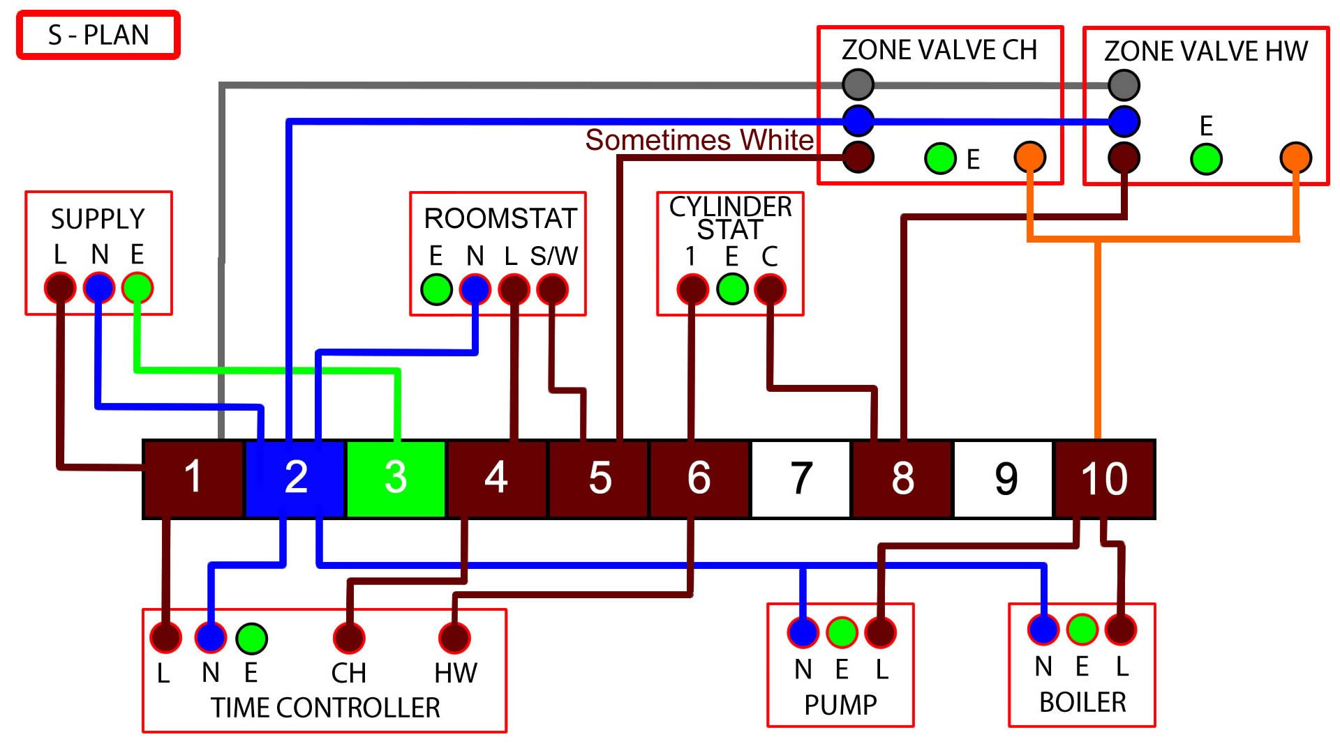
S Plan Programmer Connections S Plan central heating & hot water programmer wiring diagram, shown below 몭 rst is the cable (function) followed by the terminal number of the wiring centre. Live (L) = 1 Earth (⏚) = 2 Neutral (N) = 3 CH (on) = 4 HW (on) = 6 S Plan Power Connections S Plan power supply wiring diagram, shown below 몭 rst is the.
wiring diagram for s plan heating system Wiring Diagram

All you'll need is a 'S' plan detail and use a 3. channel programmer and two RS. Or a programmable RS. to control your second CH zone. If you know a good and I mean good Spark, they should. help. But lets face it, you are in the wrong game. mate if you can't work that one out.
Electrical paintings search result at
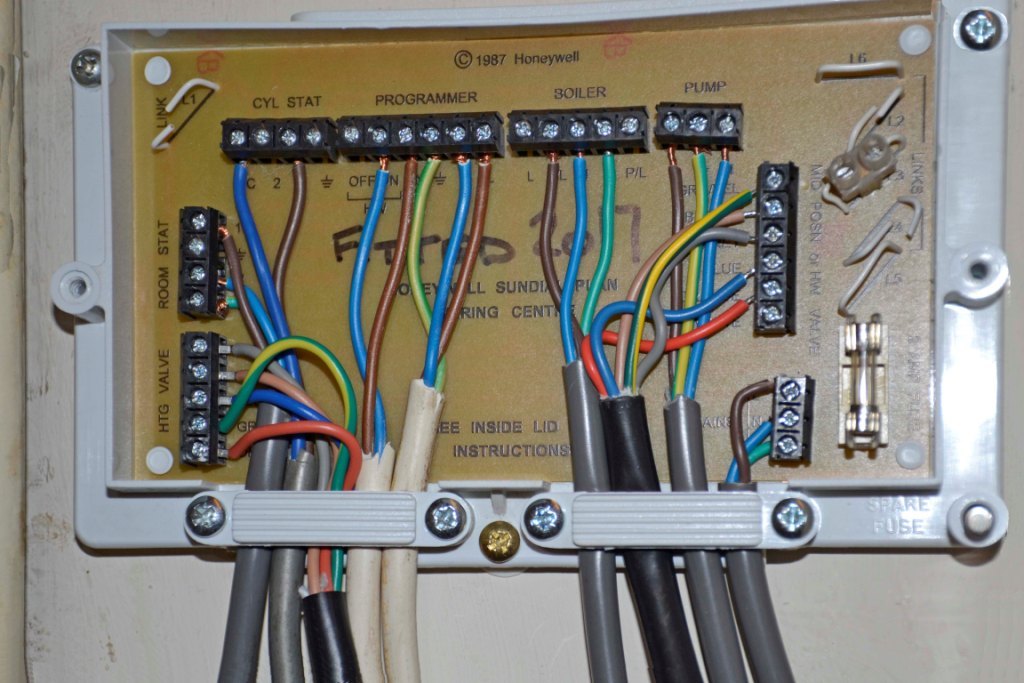
S Plan heating systems need to have a nice neat wiring center to enable everything from the plumbing up to work properly! I show you what the wires do and ho.
Wiring Diagram For Y Plan Heating System Wiring Flow Schema

S Plan Wiring Diagram 3 Zones. If you have a central heating system with three zones, you will need an S plan wiring diagram to properly connect and control the system. The S plan wiring diagram is a diagram that shows the different components and connections of the system, including the boiler, pump, zone valves, and thermostats..
3 Zone S Plan Wiring Diagram Organicid

V4043H1106 (28mm), the white wire OW must be electrically isolated. 3. The same terminal numbers are used on the receiver for both the DT92E and Y6630D wireless room thermostats. Sundial S Plan Wireless room thermostat Sundial S Plan Wireless programmable room thermostat L N 230V 50Hz 3A RATED V4043H ZONE VALVE HTG V4043H ZONE VALVE DHW E MOTOR.
S Plan Wiring Diagram 3 Zones Wiring Service

This is very similar to an S-plan system. Each zone valve is separate, and controlled by it's own thermostat. Wiring Centre. This is just a junction box with terminals inside. This one is shown with 10 terminals. In these diagrams, 1&2, 3&4, 5&6 have been linked together in pairs to make it easier to fit the wires into the terminals.
Wiring Diagram Y Plan Wiring Digital and Schematic

1. Gather the necessary materials. Before starting the wiring process, make sure you have all the necessary materials, including electrical cables, junction boxes, connectors, and Honeywell S Plan components, such as the programmer, thermostat, motorized valves, and boiler controls. 2. Follow the wiring diagram.
honeywell s plan wiring diagram Wiring Diagram
S-Plan Wiring Diagram 230V from consumer unit with 6A MCB + 30 mA RCD 0.75mm or 1.0mm TE cable DHW & CH main switch 3A Fuse Switched Live 230V from consumer unit 16A MCB + 30 mA RCD 2.5Mm or 6.0mm TE cable Power Switch 13A Fuse Heating On Hot Water On Programmer Junction Box Room Thermostat Cylinder Thermostat Hot Water Valve
3 Zone S Plan Wiring Diagram Handmadeist
Step-by-Step Guide to Reading S Plan Heating System Wiring Diagrams. 1. Introduction. Understanding the wiring diagrams for an S Plan heating system is crucial for anyone involved in installation, maintenance, or troubleshooting. These diagrams provide a visual representation of the various components and their interconnections, helping you to.
Typical Central Heating Wiring Diagram Bestn

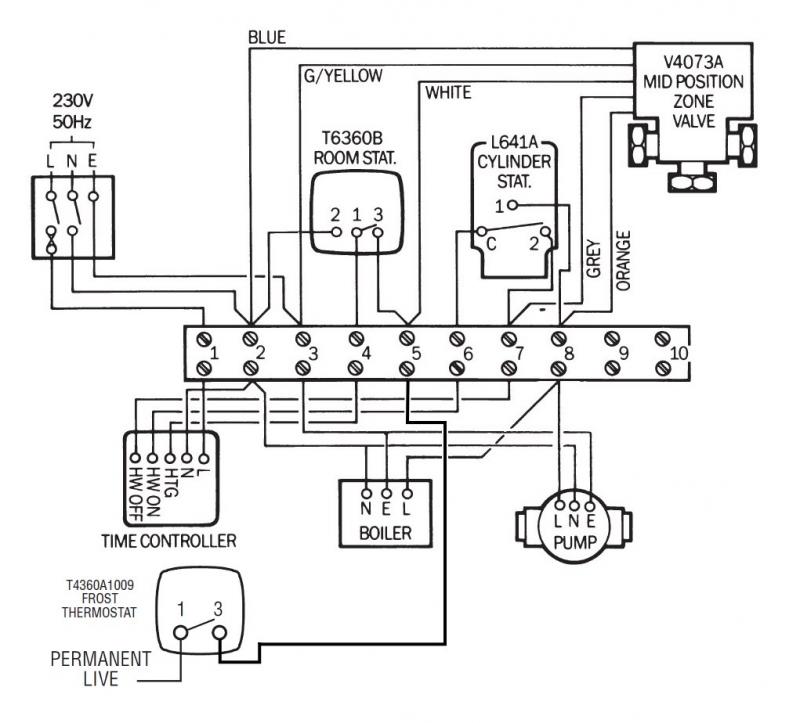
3 room stat. 2 1 3 programmer 's' plan l n htg on dhw on blue g/yellow brown grey orange blue g/yellow brown orange grey zone valve d h w v4043h x-range s' plan wiring diagram 17 16 15 14 13 12 11 10 9 8 7 6 5 4 3 2 1 x15 (24v=) x14 pc 5 4 3 2 1 5 4 3 2 1. visio-wiring diagrams book.vsd
S Plan Wiring Diagram With Frost Stat Wiring Diagram
Lofty. Dec 2, 2010. #3. Hi All, As Lenny says you may need to have either a 3 channel T/clock or add a single channel one for the UFH. What you actually have is an 'S' plan + (plus) the schematic for this can be found on the Honeywell website. If i have one I'll dig it out and post it on here. Cheers, Lofty.
Honeywell Wiring Diagram Y Plan

This video covers the wiring and electrical operation of an S plan system with two 2-port valves. Wiring diagrams and further information continues below. View on Youtube. System Wiring. This diagram shows the wiring layout using the most typical components. Here, coloured wires indicate the permanent mains supply to the boiler and programmer.
S Plan Wiring Diagram With Frost Stat Wiring Diagram and Schematic

S-Plan Wiring centre S-Plan Wiring centre 2B Typical wiring scheme for multi zone UFH with a combination boiler 3B Typical wiring scheme for single zone UFH with a combination boiler This drawing is for guidance only. All installations should be undertaken by a qualified person only. This drawing is for guidance only.
Central Heating Programmer Wiring Diagram Wiring Schematica

S Plan Hardwired Pack Wiring Diagram Page 1 of 1 Components: 1 x 2 Channel Programmer 2 x 2 Port Motorised Valve 1 x Pipe / Cylinder Thermostat 1 x Room Thermostat 1 x Wiring Centre EPH Controls Ireland sales@ephcontrols.com www.ephcontrols.com EPH Controls UK sales@ephcontrols.co.uk www.ephcontrols.co.uk 20180305_CR22_P_WD_JW SPUR FUSED @ 3A.
* Honeywell Sundial Plan Wiring Centre Central Heating Wiring Box 42005748001 eBay
This video covers the wiring and electrical operation of an S plan system with two 2-port valves. Wiring diagrams and further information continues below. View on Youtube. System Wiring. This diagram shows the wiring layout using the most typical components. Here, coloured wires indicate the permanent mains supply to the boiler and programmer.
Generator Wiring Diagram 3 Phase / 3 Phase Generator Wiring Diagram Fuse Box And Wiring

SINGLE ZONE - Wired Thermostat This equipment should be installed by an appropriately qualified/registered electrician. Fully read the instructions for proper wiring before applying power. The warranty does not cover damage from improper wiring or installation. UFH Wiring Diagram neautral earth endswitch boiler enable 5 Honeywell Temperature.
.

